 |
FEEDBACK
AND OPERATIONAL AMPLIFIERS
(Some selected section from CHAPTER
3 of the book "The Art of Electronics", written by Paul Horowitz and Winfield
Hill, Cambridge University Press , 1985.)
|
|
|
|
F - Pricíp činnosti operačného zosilňovača v zapojení komparátora a v zapojení Schmittovho preklápacieho obvodu
COMPARATORS AND SCHMITT TRIGGER
It is quite common to want to know which
of two signals is larger, or to know when a given signal exceeds a predetermined
value. For instance, the usual method of generating triangle waves is to
supply positive or negative currents into a capacitor, reversing the polarity
of the current when the amplitude reaches a preset peak value. Another
example is a digital voltmeter. In order to convert a voltage to a number,
the unknown voltage is applied to one input of a comparator, with a linear
ramp (capacitor + current source) applied to the other. A digital counter
counts cycles of an oscillator while the ramp is less than the unknown
voltage and displays the result when equality of amplitudes is reached.
The resultant count is proportional to the input voltage. This is called
singleslope
integration; in most sophisticated instruments a dual-slope
integration is used .
 |
 |
| Figure 3-51 | Figure 3-52 |
3.22 Comparators
The simplest form of comparator is a highgain differential amplifier, made either with transistors or with an op-amp (Fig. 3.51). The op-amp goes into positive or negative saturation according to the difference of the input voltages. Because the voltage gain typically exceeds 100,000, the inputs will have to be equal to a fraction of a millivolt in order for the output not to be saturated. Although an ordinary op-amp can be used as a comparator (and frequently is), there are special integrated circuits intended for use as comparators. Some examples are the LM306, LM311, LM393, and NE529. These chips are designed for very fast response and aren't even in the same league as op-amps. For example, the high speed NE521 slews at several thousand volts per microsecond. With comparators, the term "slew rate" isn't usually used; you talk instead about "propagation delay versus input overdrive."
Comparators generally have more flexible output circuits than op-amps. Whereas an ordinary op-amp uses a push-pull output stage to swing between the supply voltages (± 13V, say, for a 741 running from ± 15V supplies), a comparator chip usually has an "open-collector" output with grounded emitter. By supplying an external "pull-up" resistor (that's accepted terminology, believe it or not) connected to a voltage of your choice, you can have an output swing from + 5 volts to ground, say. You will see later that logic circuits have well-defined voltages they like to operate between; the preceding example would be ideal for driving a TTL circuit, a popular type of digital logic. Figure 3.52 shows the circuit. The output switches from +5 volts to ground when the input signal goes negative. This use of a comparator is really an example of analog-to-digital conversion.
This is the first example we have presented
of an open-collector output; this is a common configuration
in Iogic circuits. If you like, you can think of the external pull-up resistor
as completing the comparator's internal circuit by providing a collector
load resistor for an npn output transistor. Since the output transistor
operates as a saturated switch, the resistor value is not at all critical,
with values typically between a few hundred ohms and a few thousand ohms;
smaller values yield improved switching speed and noise immunity at the
expense of increased power dissipation. Incidentally, in spite of their
superficial resemblance to op-amps, comparators are never used with negative
feedback because they would not be stable (see Sections
3.31-3.33).
However, some positive feedback is often used, as you will see in
the next section.
Comments on comparators
Some points to remember:
- Since there is no negative feedback, golden rule 1 is not obeyed. The inputs are not at the same voltage.
- The absence of negative feedback means that the (differential) input impedance isn't bootstrapped to the high values characteristic of op-amp circuits. As a result, the input signal sees a changing load and changing (small) input current as the comparator switches; if the driving impedance is too high, strange things may happen.
- Some comparators permit only limited differential input swings, as little as ±5 volts in some cases.
The simple comparator circuit in Figure
3.52 has two disadvantages. For a very slowly varying input, the output
swing can be rather slow. Worse still, if the input is noisy, the output
may make several transitions as the input passes through the trigger point
(Fig. 3.53). Both these problems can be remedied by the use of positive
feedback
(Fig. 3.54). The effect of R3 is to make the circuit have
two thresholds, depending on the output state. In the example shown,
the threshold when the output is at ground (input high) is 4.76 volts,
whereas the threshold with the output at +5 volts is 5.0 volts. A noisy
input is less likely to produce multiple triggering (Fig. 3.55). Furthermore,
the positive feedback ensures a rapid output transition, regardless of
the speed of the input waveform. (A small "speedup" capacitor of 10 -100pF
is often connected across R3 to enhance switching speed still
further.) This configuration is known as a Schmitt trigger. (If an op-amp
were used, the pull-up would be omitted.) The output depends both on the
input voltage and on its recent history, an effect called hysteresis.This
can be illustrated with a diagram of output versus input, as in Figure
3.56.
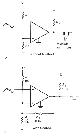
Figure 3-54 |
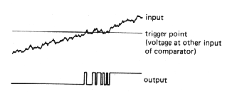
Figure 3-53 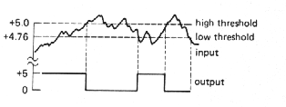
Figure 3-55 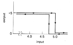
Figure 3-56 |
Discrete-transistor Schmitt trigger
A Schmitt trigger can also be made simply
with transistors (Fig. 3.57). Q1 and Q2 share an
emitter resistor. It is essential that Q1's collector resistor
be larger than Q2's. In that way the threshold to turn on Q1,
which is one diode drop above the emitter voltage, rises when Q1
is turned off, since the emitter current is higher with Q2 conducting.
This produces hysteresis in the trigger threshold, just as in the preceding
integrated-circuit Schmitt trigger.
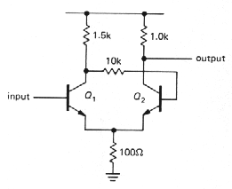 |
Figure 3-57 |
| Back to menu |