 |
FEEDBACK
AND OPERATIONAL AMPLIFIERS
(Some selected section from CHAPTER
3 of the book "The Art of Electronics", written by Paul Horowitz and Winfield
Hill, Cambridge University Press , 1985.)
|
|
|
|
FEEDBACK AMPLIFIER FREQUENCY COMPENSATION
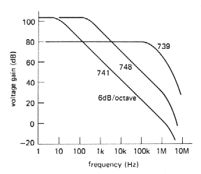
If you look at graph of open voltage gain versus frequency for several op-amps, you'll see something like the curves in Figure 3.70. From a superficial look at such a Bode plot (a log-log plot of gain and phase versus frequency) you might conclude that the 741 is an inferior op-amp, since its open-loop gain drops off so rapidly with increasing frequency. In fact, that rolloff is built into the op-amp intentionally and is recognizable as the same -6dB/octave curve characteristic of an RC low-pass filter. The 748, by comparison, is identical to the 741 except that it is uncompensated (as is the 739). Op-amps are generally available in internally compensated varieties and uncompensated varieties; let's take a look at this business of frequency compensation.
 |
.
Figure 3-70 |
3.31 Gain and phase shift versus frequency
An op-amp (or, in general, any multistage amplifier) will begin to roll off at some frequency because of the low-pass filters formed by signals of finite source impedance driving capacitive loads within the amplifier stages. For instance, it is common to have an input stage consisting of a differential amplifier, perhaps with current mirror load, driving a common-emitter second stage. The high output impedance of the input stage, in combination with junction capacitance Cie and feedback capacitance Ccb (Miller effect) of the following stage, forms a low-pass filter whose 3dB point might fall somewhere in the range of 100Hz to 10kHz.
The decreasing reactance of the capacitor with increasing frequency gives rise to the characteristic 6dB/octave rolloff: At sufficiently high frequencies (which may be below 1kHz), the capacitive loading dominates the collector load impedance, resulting in a voltage gain GV= gmXC, i.e., the gain drops off as 1/f. It also produces a 90° lagging phase shift at the output relative to the input signal. (You can think of this as the tail of an RC low-pass filter characteristic, where R represents the equivalent source impedance driving the capacitive load. However, it is not necessary to have any actual resistors in the circuit.)
 |
.
Figure 3-71 |
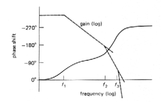
In a multistage amplifier there will be additional rolloffs at higher frequencies, caused by low-pass filter characteristics in the other amplifier stages, and the overall open-loop gain will look something like that shown in Figure. 3.71. The open-loop gain begins dropping at 6dB/octave at some low trequency f1, due to capacitive loading of the first-stage output. It continues dropping off with that slope until an internal RC of another stage rears its ugly head at frequency f2, beyond which the rolloff goes at 12dB/octave, and so on.
 |
.
Figure 3-72 |
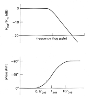
What is the significance of all this? Remember that an RC low-pass filter has a phase shift that looks as shown in Figure 3.72. Each low-pass filter within the amplifier has a similar phase shift characteristic, so the overall phase shift of the hypothetical amplifier will be as shown in Figure 3.73.
 |
.
Figure 3-73 |
Now here's the problem: If you were to
connect this amplifier as an op-amp follower, for instance, it would oscillate.
That's because the open-loop phase shift reaches 180° at some frequency
at which the gain is still greater than one (negative feedback becomes
positive feedback at that frequency). That's all you need to generate an
oscillation, since any signal whatsoever at that frequency builds up each
time around the feedback loop, just like a public address system with the
gain turned up too far.
Stability criterion
The criterion for stability against oscillation for a feedback amplifier is that its open-loop phase shift must be less than 180° at the frequency at which the loop gain (in the feedback configuration) is unity. This criterion is hardest to satisfy when the amplifier is connected as a follower, since the loop gain then equals the open-loop gain, the highest it can be. Internally compensated op-amps are designed to satisfy the stability criterion even when connected as folowers; thus they are stable when connected for any closed-loop gain with a simple resistive feedback network. As we hinted earlier, this is accomplished by deliberately modifying an existing internal rolloff in order to put the 3dB point at some low frequency, typically 1 Hz to 20Hz. Let's see how that works.
 |
.
Figure 3-74 |
3.32 Amplifier compensation
methods
Dominant-pole compensation
The goal is to keep the open-loop phase shift much less than 180° at all frequencies for which the loop gain is greater than 1. Assuming that the op-amp may be used as a follower, the words "loop gain" in the last sentence can be replaced by "open-loop gain." The easiest way to do this is to add enough capacitance at the point in the circuit that produces the initial 6dB/octave rolloff, so that the open-loop gain drops to unity at about the 3dB frequency of the next "natural" RC filter. In this way the open-loop phase shift is held at a constant 90° over most of the passband, increasing toward 180° only as the gain approaches unity. Figure 3.74 shows the idea. Without compensation the open-loop gain drops toward 1, first at 6dB/octave, then at 12dB/octave, etc., resulting in phase shifts of 180° or more before the gain has reached 1. By moving the first rolloff down in frequency (forming a "dominant pole"), the rolloff is controlled so that the phase shift begins to rise above 90° only as the openloop gain approaches unity. Thus, by sacrificing open-loop - gain, you buy stability. Since the natural rolloff of lowest frequency is usually caused by Miller effect in the stage driven by the input differential amplifier, the usual method of dominant-pole compensation consists simply of adding additional feedback capacitance around the secondstage transistor, so that the combined voltage gain of the two stages is gmXC or gm /2pfCcomp over the compensated region of the amplifier's frequency response (Fig. 3.75). In practice, Darlington-connected transistors would probably be used for both stages.
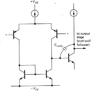 |
Figure 3-75 |
By putting the dominant-pole unity-gain crossing at the 3dB point of the next rolloff, you get a phase margin of about 45 ° in the worst case (follower), since a single RC filter has a 45° lagging phase shift at its 3dB frequency, i.e., the phase margin equals 180° - (90° + 45°), with the 90° coming from the dominant pole.
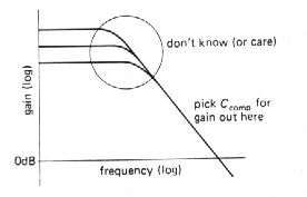 |
Figure 3-76 |
An additional advantage of using a Miller
- effect pole for compensation is that the compensation is inherently insensitive
to changes in voltage gain with temperature, or manufacturing spread of
gain: Higher gain causes the feedback capacitance to look larger, moving
the pole downward in frequency in exactly the right way to keep the unity-gain
crossing frequency unchanged. In fact, the actual 3dB frequency of the
compensation pole is quite irrelevant; what matters is the point at which
it intersects the unity-gain axis (Fig. 3.76).
Uncompensated op-amps
If an op-amp is used in a circuit with closed-loop gain greater than 1 (i.e., not a follower), it is not necessary to put the pole (the term for the "corner frequency" of a low-pass filter) at such a low frequency, since the stability criterion is relaxed because of the lower loop gain. Figure 3.77 shows the situation graphically.
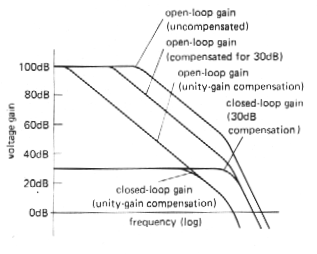 |
Figure 3-77 |
For a closed-loop gain of 30dB, the loop gain (which is the ratio of the open-loop gain to the closed-loop gain) is less than for a follower, so the dominant pole can be placed at a higher frequency. It is chosen so that the open-loop gain reaches 30dB (rather than 0dB) at the frequency of the next natural pole of the op-amp. As the graph shows, this means that the open-loop gain is higher over most of the frequency range, and the resultant amplifier will work at higher frequencies. Most op-amps are available in uncompensated versions [e.g., the 748 is an uncompensated 741: the same is true for the 308 (312), 3130 (3160), etc], with recommended external capacitance values for a selection of minimum closed-loop gains. They are worth using if you need the added bandwidth and your circuit operates at high gain. An alternative is to use "decompensated" (a better word might be "undercompensated") op-amps such as the 349 or 357, which are internally compensated for closed-loop gains greater than some minimum (AV > 5 in the case of the 349 and 357).
 |
.
Figure 3-78 |
l Pole-zero compensation
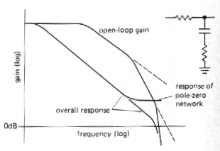
It is possible to do a bit better than
with dominant-pole compensation by using a compensation network that begins
dropping (6dB/octave, a "pole") at some low frequency, then flattens out
again (it has a "zero"') at the frequency of the second natural pole of
the op-amp. In this way the amplifier's second pole is "canceled," giving
a smooth 6dB/octave rolloff up to the amplifier's third pole. Figure 3.78
shows a frequency response plot. In practice, the zero is chosen to cancel
the amplifier': second pole; then the position of the first pole is adjusted
so that the overall response reaches unity gain at the frequency of the
amplifier's third pole. A good set of data sheets will often give suggested
component values (an R and a C) for pole-zero-compensation, as well as
the usual capacitor value~ for dominant-pole compensation.
l
3.33 Frequency response of the feedback network
In all of the discussion thus far we hav assumed that the feedback network has flat frequency response; this is usually the case, with the standard resistive voltage divider as a feedback network. However, there are occasions when some sort of equalization amplifier is desired (integrators and differentiators are in this category) or when the frequency response of the feedback network is modified to improve amplifier stability. In such cases it is important to remember that the Bode plot of loop gain versus frequency is what matters, rather than the curve of open-loop gain. To make a long story short, the curve of ideal closed-loop gain versus frequency should intersect the curve of open-loop gain with a difference in slopes of 6dB/octave. As an example, it is common practice to put a small capacitor (a few picofarads) across the feedback resistor in the usual inverting or noninverting amplifier. Figure 3.79 shows the circuit and Bode plot.
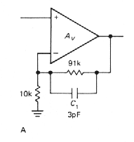
Figure 3-79 |
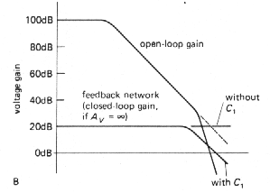 |
The amplifier would have been close to
instability with a flat feedback network, since the loop gain would have
been dropping at nearly 12dB/octave where the curves meet. The capacitor
causes the loop gain to drop at 6dB/octave near the crossing, guaranteeing
stability. This sort of consideration is very important when designing
differentiators, since an ideal differentiator has a closed-loop gain that
rises at 6dB/octave; it is necessary to roll off the differentiator action
at some moderate frequency, preferably going over to a 6dB/octave rolloff
at high frequencies. Integrators, by comparison, are very friendly in this
respect, owing to their 6dB/octave closed-loop rolloff. It takes real talent
to make a low-frequency integrator oscillate!
F - Iný pohľad na korekčné obvody pre zosilňovač so spätnou väzbou
l What to do
In summary, you are generally faced with
the choice of internally compensated or uncompensated op-amps. It is simplest
to use the compensated variety, and that's the usual choice. At the present
time the internally compensated 741 is by far the most popular op-amp.
If you need greater bandwidth or slew rate, and the closed-loop gain is
greater than unity (as it usually is), you can either use an uncompensated
op-amp with an external capacitor (and possibly a resistor), as specified
by the manufacturer for the gain you are using, or simply choose a faster
compensated op-amp. Several amplifiers, including the popular 356 op-amp,
offer another choice: a decompensated version (the 357) with internal compensation
good for a closed-loop gain of 5 or more.
| Back to menu |