| Transmission lines |
Coaxial cable gives very good eprotection against interference, because of its completely shielding geometry.
Transmission lines (TL) play central role in nuclear physics experiments, where they are used to pipe signals around from one place to another within a circuits, and often from the preamplifier output to input of the pulse shaper or fast amplifier.
TL for signal of frequencies up to 1GHz comes in 2 major types:
- Parallel type of conductor line
- Coaxial line (widely used e.g in short lengths with BNC fitting to carry signal between instruments.)
 |
| Example of the various TL: (a) coaxial cable, (b) twin lead |
In the domain of ultra-high frequency circuitry there are "strip-line" techniques used. In "microwave range" of frequency (upwards of 2GHz) conventional TL is replaced by cavity and wave-guide techniques. For nuclear physics applications the familiar coax is probable the best choice.
By processing short duration's pulses , or fast rise pulses is observed that speed of electromagnetic wave propagation => transmission depends on geometrical configuration (layout) of electronics details.
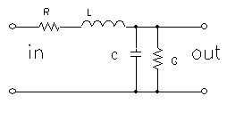
When we consider a wave with frequency f propagating in transmission medium with dielectric constant e with velocity v=c/e (c-velocity of light in space) then its wavelength can be calculated l =v/f~c/f. (For example for 100MHz l =3m.) Electronic properties of TL are no more lumped, or focused to 1 point, but (R, L, C, G of line) are continually distributed in space, and are depending on distance x too: => u(t,x), i(t,x).
TL must be considered as a circuit with distributed parameters.
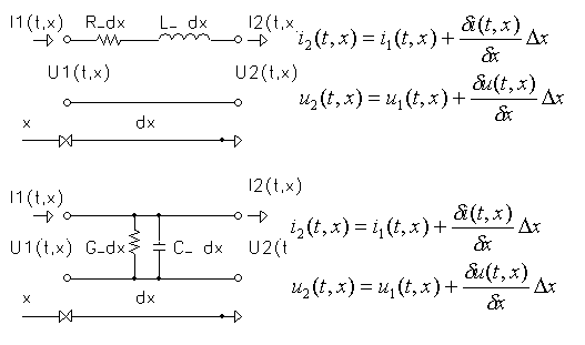
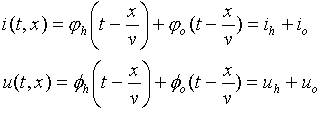
Homogenous unit part of the TL can be characterized their (R, L, C, G of line) per meter. The differential equation leads to solution based on superposition of 2 waves:
- main (proceeding, in advance moving, shifting),and
- reflected.
 |
Equivalent unit part of the TL |
 |
Distribution
of u(t,x),
i(t,x) in unit part of the TL.
|
 |
Differential "telegraph" equation based on distribution u(t,x), i(t,x ) according fig. above. |
 |
Solution
of the differential
"telegraph" equation based on superposition of 2 waves:
|
In any section of TL characteristic impedance Z0, which well described properties of TL as a ratio of voltage wave to current wave (equal Z0)
For short part of TL, such line with R=0 and G=infinite can be assumed as a loss-less line and Z0=(L/C)0.5 =>resistive in range 50 to 100 ohm.
A
part TL of length d can be
used as element
of delay line with delay T =d(LC)0.5.
 |
Time delaying property T=d/v of the TL |
| Mismatched transmission lines |
When TL is used in high frequency range (or pulse with short rise time) signals, it is important to "match" the load to the characteristic impedance of the line. The following facts are important:
- A transmission line terminated with a load equal to its characteristic impedance (resistance) will transfer an applied pulse to termination without reflection. In that case all the power in the signal is transferred to the load.
- The impedance looking into such a terminated line, at any signal's frequency, is equal to its characteristic impedance.
 |
Properties of a mismatched TL. |
The ratio
of reflected wave amplitude to
incident
wave amplitude is given by
| r= Ao/Ah=(R- Z0)/(R+ Z0). |
Similarly as coefficient of reflection r
is a coefficient of (voltage) radiation s1
and s2 (current)
defined:
. .
| s1=(2Z)/(Z+ Z0)=1+r | |
| s2=(2Z0)/(Z+ Z0)=1-r |
A line terminated in a short circuits
produced
a reflected wave determined by the electrical length of the line. (A
speed
of the wave propagation in coax lines is about two-thirds the light
speed
=> 1m thin coax delays ~5ns)
 |
The reflected wave is inverted if R<Z0 |
In similar manner, an open-circuited
cable
(boundary condition of zero current at the end) produces a non-inverted
reflection of amplitude equal to the applied signal.
 |
The reflected wave is non-inverted if R>Z0. |
Cables terminated with a resistance R
unequal
to characteristic resistance also produce reflections, although of
lesser
amplitude.
 |
The
reflected wave at:
|
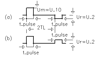
This property of shorted cable part is sometimes exploited to generate a short pulse from step wave's form. The step input is applied the cable input through a resistance equal to Z0, with the other end of the cable shortened. The pulse wave's form at the input is then a pulse of width equal to the round-trip travel time, since the reflected step pulse cancels the input step.
In nuclear physics experiments is
dangerous to
forget some open-circuits cable, which can then help to generate a
false
pulses and so make distortion in pulse high amplitude.
 |
![]()
|
|
Back to previous page |