| Frequency response of linear amplifiers |
Problem how to design of amplifiers which give uniform gain and phase delay over the frequency pass - band. For example: pass - band in region:
- 20 Hz - 100 kHz for audio amplifiers
- 0 - 4,5 MHz for video amplifiers.
Most circuits for pulse shaping are based on the chain RC and transmission lines. Before proceeding to the subject of pulse processing I will deal briefly with the RC passive filters and with other interesting subject of transmission lines
![]()
| Passive Filters |
|
|
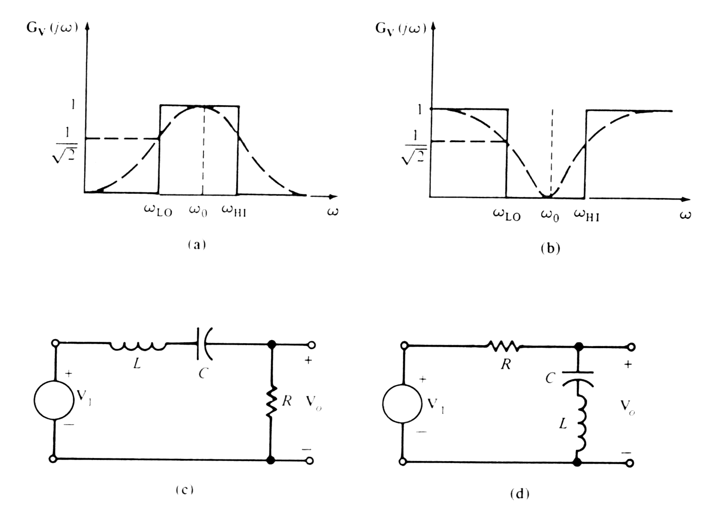
Low - pass filter - pass low frequencies and reject high frequencies. |
|
|
High - pass filter - pass high frequencies and reject low frequencies. |
|
|
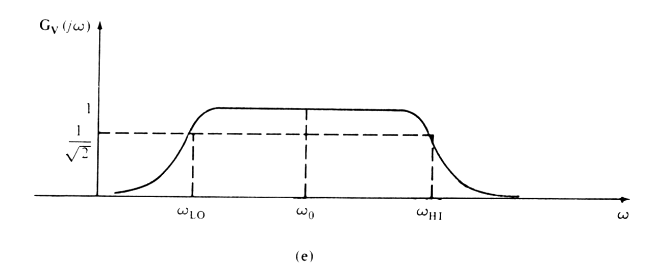
Band - pass filter - pass some particular band of frequencies and reject all frequencies outside the range. |
|
|
Band - rejection filter
-
specifically designed to reject a particular band of frequencies and pass
some other frequencies.
Typical or physically realized characteristic are different from ideal frequency characteristic ( to pass all frequencies to some frequency w0=2pf0 and pass no frequencies above that value. Reason why is not possible to design such ideal filter with linear circuits elements. |
|
|
Break frequency - (1/(2)0.5 ) - half - power frequency. The name derived from the fact that voltage (U/(2)0.5 ) or current (I/(2)0.5 ) => power is proportional to the square of U or I, is one-half of its maximum value. |
![]()
| RC filter |
![]()
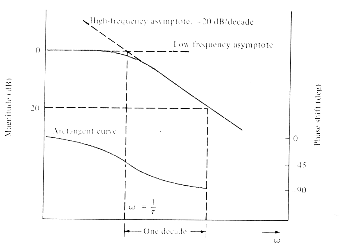
The magnitude in dB [=> logarithmic scale].
Magnitude curve is flat for low frequency and rolls off at high frequency.
The phase shifts from 0o to 90o at high frequencies.
 |
 |
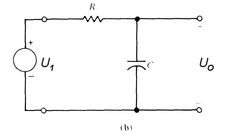 |
|
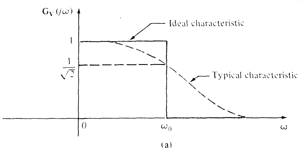 |
Low-pass filter circuit (RC circuit) and frequency
characteristic.
|
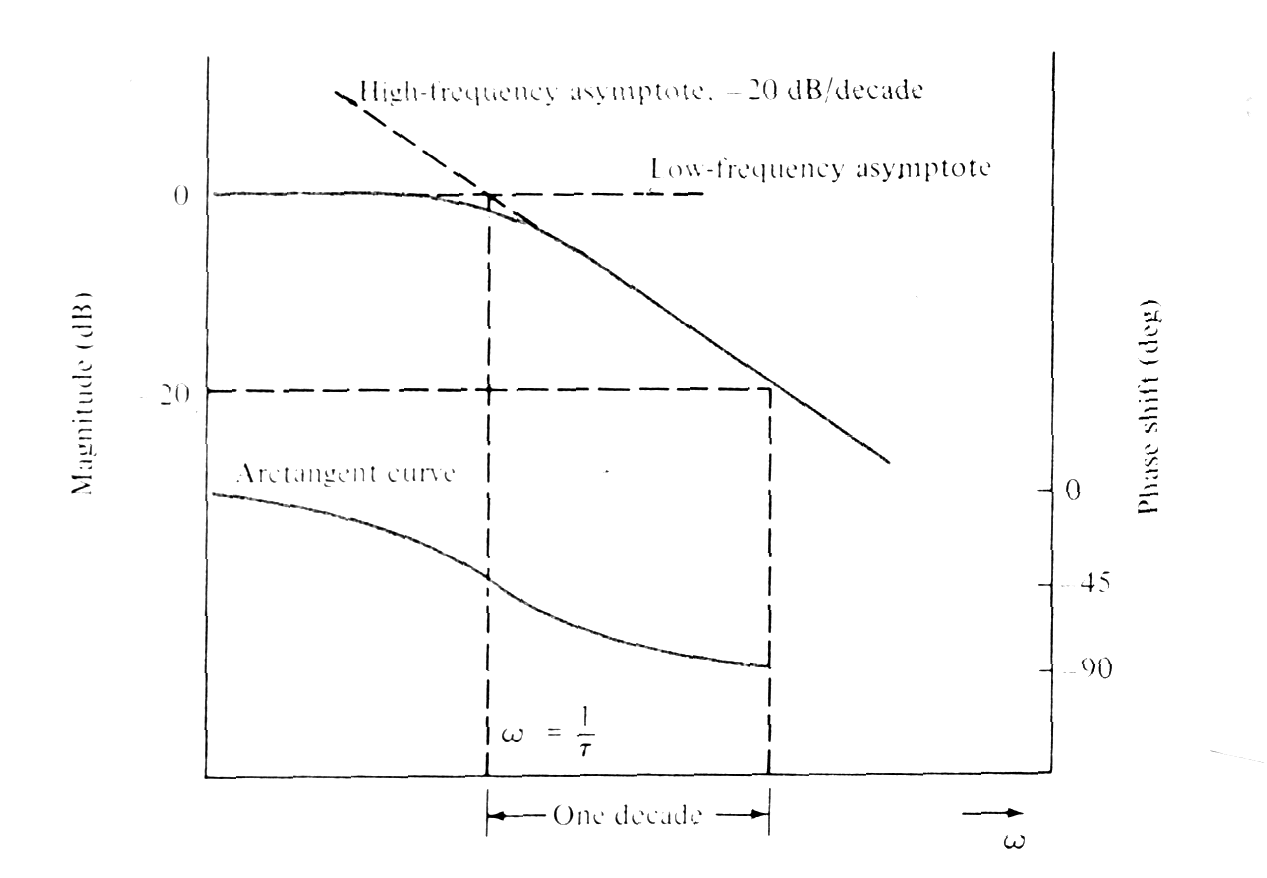 |
(Low-frequency asymptote 0dB/decade, high-frequency asymptote - 20dB/decade). Phase shift characteristic (arctangent curve) has pulse shift 45deg at frequency w=1/t. |
![]()
| CR filter |
Ideal high - pass filter passes all frequencies
above some frequency w0
=1/t
, j(w0)=45o
and no frequencies bellow that value. At low frequencies the magnitude
has slope +20dB/decade due to term wt
in the numerator.
 |
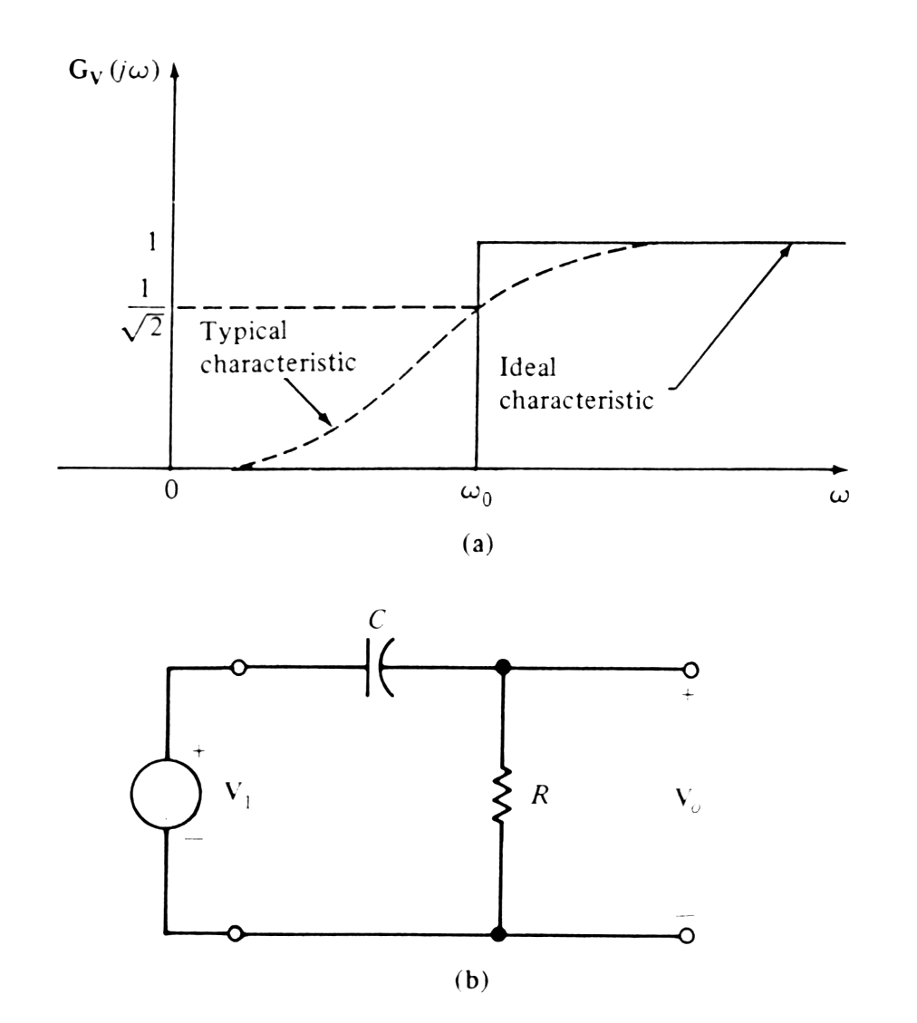 |
High-pass filter circuit (CR circuit) and frequency characteristic. |
 |
(Low-frequency asymptote 0dB/decade, high-frequency asymptote - 20dB/decade). Phase shift characteristic (arctangent curve) has pulse shift 45deg at frequency w=1/t. |
Simple networks are capable of realizing characteristics with w0 as a center frequency of pass or rejection band and the frequency wL0, wH0 at which the maximum or minimum occurs is called cutoff frequency ( lower / upper break frequency)
The width of the pass / rejection band - bandwidth
BW = wH0 -wL0
 |
 |
![]()
| Frequency domain vs. time domain |
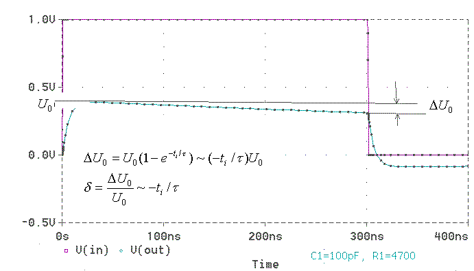
Considering the response of pass CR filter to rectangular pulse in time domain (a rectangular pulse generated as a positive step function at t = 0 s and a negative step function to the end of duration of a pulse) we will obtain a sag of the pulse with duration ti. For small x<<1 is 1-exp(-x) ~x and the exponential function can be replaced with the first terms of its series
 |
| Allowable slope of the pulse hight after shaping rectangular pulse |
Small sag is obtained by making td=CR large with respect to the pulse duration (=> ti/td is small).From low frequency band limit definition wd=2pfd=1/td=1/RC. The ratio terms of shape that sags d=DU0/U0=ti/td=ti2pfd.
Relation between frequency domain characteristic and time domain response characteristic
fd=d/2pti
=> for small sag (<< 10%) is necessary small fd.
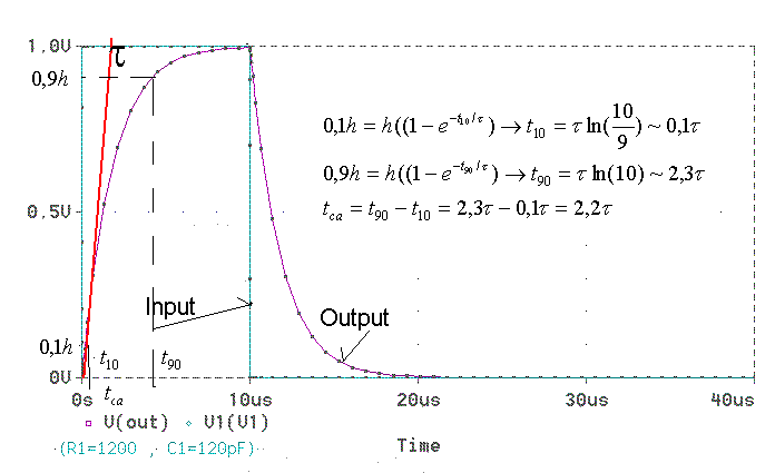
The rise time dependents on the pulse transfer in the high frequencies characteristic region or rise time is due to frequency distortion. If the leading edge of the input pulse is a step function then the output rise time (measured at 10% level t10 and 90% level t90 is defined tra=t90-t10=2.3 ti-0.1ti=2.2ti. Considering that RC circuits is law-pass device with upper break frequency wi=2pfi=1/ti=1/RC and ti=RC=tra/(2.2), then relation between rise time tra and upper break frequency
fi=(2.2)/2ptra ~ (0.35)/tra
 |
| Determinating of the active pulse rise time tra |
![]()
|
|
Back to previous page |